Plane Poiseuille flow - BVP

| categories: odes | View Comments

Plane Poiseuille flow - BVP

Plane Poiseuille flow - BVP

in the pressure driven flow of a fluid with viscosity $\mu$ between two stationary plates separated by distance $d$ and driven by a pressure drop $\Delta P/\Delta x$, the governing equations on the velocity $u$ of the fluid are (assuming flow in the x-direction with the velocity varying only in the y-direction):

$$\frac{\Delta P}{\Delta x} = \mu \frac{d^2u}{dy^2}$$

with boundary conditions $u(y=0) = 0$ and $u(y=d) = 0$, i.e. the no-slip condition at the edges of the plate.

we convert this second order BVP to a system of ODEs by letting $u_1 = u$, $u_2 = u_1'$ and then $u_2' = u_1''$. This leads to:

$\frac{d u_1}{dy} = u_2$

$\frac{d u_2}{dy} = \frac{1}{\mu}\frac{\Delta P}{\Delta x}$

with boundary conditions $u_1(y=0) = 0$ and $u_1(y=d) = 0$.

for this problem we let the plate separation be d=0.1, the viscosity $\mu = 1$, and $\frac{\Delta P}{\Delta x} = -100$.

function main
clc; close all; clear all;

d = 0.1; % plate thickness

we start by defining an initial grid to get the solution on

x = linspace(0,d);

Next, we use the bvpinit command to provide an initial guess using the guess function defined below

solinit = bvpinit(x,@guess);

we also need to define the ode function (see odefun below).

and a boundary condition function (see bcfun below).

now we can get the solution.

sol = bvp5c(@odefun,@bcfun,solinit)
sol = 

    solver: 'bvp5c'
         x: [1x100 double]
         y: [2x100 double]
     idata: [1x1 struct]
     stats: [1x1 struct]

sol is a Matlab struct with fields. the x field contains the x-values of the solution as a row vector, the y field contains the solutions to the odes. Recall that U1 is the only solution we care about, as it is the original u(x) we were interested in.

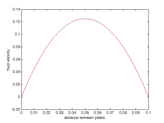
y = sol.x;
u1 = sol.y(1,:);
u2 = sol.y(2,:);
plot(y,u1); figure(gcf)
xlabel('distance between plates')
ylabel('fluid velocity')

% the analytical solution to this problem is known, and we can plot it on
% top of the numerical solution
mu = 1;
Pdrop = -100; % this is DeltaP/Deltax
u = -(Pdrop)*d^2/2/mu*(y/d-(y/d).^2);
hold on
plot(y,u,'r--')

As we would expect, the solutions agree, and show that the velocity profile is parabolic, with a maximum in the middle of the two plates. You can also see that the velocity at each boundary is zero, as required by the boundary conditions

function Uinit = guess(x)
% this is an initial guess of the solution. We need to provide a guess of
% what the function values of u1(y) and u2(y) are for a value of y. In some
% cases, this initial guess may affect the ability of the solver to get a
% solution. In this example, we guess that u1 and u2 are constants
U1 = 0.1;
U2 = 0;
Uinit = [U1; U2]; % we return a column vector

function dUdy = odefun(y,U)
% here we define our differential equations
u1 = U(1);
u2 = U(2);

mu = 1;
Pdrop = -100; % this is DeltaP/Deltax
du1dy = u2;
du2dy = 1/mu*Pdrop;
dUdy = [du1dy; du2dy];

function res = bcfun(U_0,U_d)
% this function defines the boundary conditions for each ode.
% we define the velocity at y=0 and y=d to be zero here. If the plates are
% moving, you would substitute the velocity of each plate for the zeros.
res = [0 - U_0(1);
       0 - U_d(1)];

% categories: ODEs
% tags: math, fluids
Read and Post Comments

Boundary value problem in heat conduction

| categories: odes | View Comments

Boundary value problem in heat conduction

Boundary value problem in heat conduction

For steady state heat conduction the temperature distribution in one-dimension is governed by the Laplace equation:

$$ \nabla^2 T = 0$$

with boundary conditions that at $T(x=a) = T_A$ and $T(x=L) = T_B$. To solve this in Matlab, we need to convert the second order differential equation into a system of first order ODEs, and use the bvp5c command to get a numerical solution.

the analytical solution is not difficult here: $T =  T_A-\frac{T_A-T_B}{L}x$
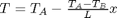
. but the bvp5c syntax takes a lot to get used to.

For this problem, lets consider a slab that is defined by x=0 to x=L, with T(x=0) = 100, and T(x=L) = 200. We want to find the function T(x) inside the slab.

To get the system of ODEs, let $T_1 = T$, and $T_2 = T_1'$. That leads to $T_2' = T_1''$ and the following set of equations:

$\frac{dT_1}{dx} = T_2$

$\frac{dT_2}{dx} = 0$

with boundary conditions $T_1(0) = 100$ and $T_1(L) = 200$. By inspection you can see that whatever value $T_2$ has, it will remain constant since the derivative of
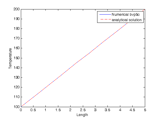
 $T_2$ is equal to zero.

function main

we start by defining an initial grid to get the solution on

x = linspace(0,5,10);

Next, we use the bvpinit command to provide an initial guess using the guess function defined below

solinit = bvpinit(x,@guess);

we also need to define the ode function (see odefun below).

and a boundary condition function (see bcfun below).

now we can get the solution.

sol = bvp5c(@odefun,@bcfun,solinit)
sol = 

    solver: 'bvp5c'
         x: [0 0.5556 1.1111 1.6667 2.2222 2.7778 3.3333 3.8889 4.4444 5]
         y: [2x10 double]
     idata: [1x1 struct]
     stats: [1x1 struct]

sol is a Matlab struct with fields. the x field contains the x-values of the solution as a row vector, the y field contains the solutions to the odes. Recall that T1 is the only solution we care about, as it is the original T(x) we were interested in.

x = sol.x;
T1 = sol.y(1,:);
T2 = sol.y(2,:);
plot(x,T1); figure(gcf)
xlabel('Length')
ylabel('Temperature')

% for demonstration we add the analytical solution to the plot
hold on
Ta = 100; Tb = 200; L = 5;
plot(x,Ta - (Ta-Tb)/L*x,'r--')
legend 'Numerical bvp5c' 'analytical solution'

As we would expect, the solutions agree, and show that the temperature changes linearly from the temperature at x=0 to the temperature at x=L.

the stats field gives you some information about the solver, number of function evaluations and maximum errors

sol.stats
ans = 

    nmeshpoints: 10
         maxerr: 9.8021e-016
      nODEevals: 106
       nBCevals: 9

function Tinit = guess(x)
% this is an initial guess of the solution. We need to provide a guess of
% what the function values of T1(x) and T2(x) are for a value of x. In some
% cases, this initial guess may affect the ability of the solver to get a
% solution. In this example, we guess that T1 is a constant and average
% value between 100 and 200. In this example, it also does not matter what
% T2 is, because it never changes.
T1 = 150;
T2 = 1;
Tinit = [T1; T2]; % we return a column vector

function dTdx = odefun(x,T)
% here we define our differential equations
T1 = T(1);
T2 = T(2);

dT1dx = T2;
dT2dx = 0;

dTdx = [dT1dx; dT2dx];

function res = bcfun(T_0,T_L)
% this function defines the boundary conditions for each ode. In this
% example, T_O = [T1(0)  T2(0)], and T_L = [T1(L) T2(L)]. The function
% computes a residual, which is the difference of what the current solution
% at the boundary conditions are vs. what they are supposed to be.  We want
% T1(0) = 100; and T1(L)=200. There are no requirements on the boundary
% values for T2 in this example.
res = [100 - T_0(1);
       200 - T_L(1)];

% categories: ODEs
% tags: math, heat transfer
Read and Post Comments

Phase portraits of a system of ODEs

| categories: odes | View Comments

ode_pendulum_phase_portrait

Contents

Phase portraits of a system of ODEs

adapted from http://www-users.math.umd.edu/~tvp/246/matlabode2.html

clear all; close all; clc

Problem setup

An undamped pendulum with no driving force is described by

$$ y'' + sin(y) = 0$$

We reduce this to standard matlab form of a system of first order ODEs by letting $y_1 = y$ and $y_2=y_1'$. This leads to:

$y_1' = y_2$

$y_2' = -sin(y_1)$

The phase portrait is a plot of a vector field which qualitatively shows how the solutions to these equations will go from a given starting point. here is our definition of the differential equations:

f = @(t,Y) [Y(2); -sin(Y(1))];

To generate the phase portrait, we need to compute the derivatives $y_1'$ and $y_2'$ at $t=0$ on a grid over the range of values for $y_1$ and $y_2$ we are interested in. We will plot the derivatives as a vector at each (y1, y2) which will show us the initial direction from each point. We will examine the solutions over the range -2 < y1 < 8, and -2 < y2 < 2 for y2, and create a grid of 20x20 points.
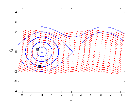
y1 = linspace(-2,8,20);
y2 = linspace(-2,2,20);

% creates two matrices one for all the x-values on the grid, and one for
% all the y-values on the grid. Note that x and y are matrices of the same
% size and shape, in this case 20 rows and 20 columns
[x,y] = meshgrid(y1,y2);
size(x)
size(y)
ans =

    20    20


ans =

    20    20

computing the vector field

we need to generate two matrices, u and v. u will contain the value of y1' at each x and y position, while v will contain the value of y2' at each x and y position of our grid.

we preallocate the arrays so they have the right size and shape

u = zeros(size(x));
v = zeros(size(x));

% we can use a single loop over each element to compute the derivatives at
% each point (y1, y2)
t=0; % we want the derivatives at each point at t=0, i.e. the starting time
for i = 1:numel(x)
    Yprime = f(t,[x(i); y(i)]);
    u(i) = Yprime(1);
    v(i) = Yprime(2);
end

now we use the quiver command to plot our vector field

quiver(x,y,u,v,'r'); figure(gcf)
xlabel('y_1')
ylabel('y_2')
axis tight equal;

Plotting solutions on the vector field

Let's plot a few solutions on the vector field. We will consider the solutions where y1(0)=0, and values of y2(0) = [0 0.5 1 1.5 2 2.5], in otherwords we start the pendulum at an angle of zero, with some angular velocity.

hold on
for y20 = [0 0.5 1 1.5 2 2.5]
    [ts,ys] = ode45(f,[0,50],[0;y20]);
    plot(ys(:,1),ys(:,2))
    plot(ys(1,1),ys(1,2),'bo') % starting point
    plot(ys(end,1),ys(end,2),'ks') % ending point
end
hold off

what do these figures mean? For starting points near the origin, and small velocities, the pendulum goes into a stable limit cycle. For others, the trajectory appears to fly off into y1 space. Recall that y1 is an angle that has values from $-\pi$ to $\pi$. The y1 data in this case is not wrapped around to be in this range.

'done'


% categories: ODEs
% tags: math
% post_id = 799; %delete this line to force new post;
ans =

done

Read and Post Comments

Solving Bessel's Equation numerically

| categories: odes | View Comments

Solving Bessel's Equation numerically

Solving Bessel's Equation numerically

Reference Ch 5.5 Kreysig, Advanced Engineering Mathematics, 9th ed.

Bessel's equation $x^2 y'' + x y' + (x^2 - \nu^2)y=0$ comes up often in engineering problems such as heat transfer. The solutions to this equation are the Bessel functions. To solve this equation numerically, we must convert it to a system of first order ODEs. This can be done by letting $z = y'$ and $z' = y''$ and performing the change of variables:

$$ y' = z$$

$$ z' = \frac{1}{x^2}(-x z - (x^2 - \nu^2) y$$

if we take the case where $\nu = 0$, the solution is known to be the Bessel function $J_0(x)$, which is represented in Matlab as besselj(0,x). The initial conditions for this problem are: $y(0) = 1$ and $y'(0)=0$.

function bessel_ode
clear all; close all; clc;
% define the initial conditions
y0 = 1;
z0 = 0;
Y0 = [y0 z0];

There is a problem with our system of ODEs at x=0. Because of the $1/x^2$ term, the ODEs are not defined at x=0.

fbessel(0,Y0)
ans =

     0
   NaN

if we start very close to zero instead, we avoid the problem

fbessel(1e-15,Y0)
ans =

     0
    -1

xspan = [1e-15 10];
[x,Y] = ode45(@fbessel, xspan, Y0);

figure
hold on
plot(x,Y(:,1),'b-');
plot(x,besselj(0,x),'r--')
legend 'Numerical solution' 'analytical J_0(x)'

You can see the numerical and analytical solutions overlap, indicating they are the same.

'done'
ans =

done

function dYdx = fbessel(x,Y)
% definition of the Bessel equation as a system of first order ODEs
nu = 0;

y = Y(1);
z = Y(2);

dydx = z;
dzdx = 1/x^2*(-x*z - (x^2 - nu^2)*y);

dYdx = [dydx; dzdx];

% categories: ODEs
% tags: math
% post_id = 763; %delete this line to force new post;
Read and Post Comments

first order reversible reaction in batch reactor

| categories: odes | View Comments

first order reversible reaction in batch reactor

first order reversible reaction in batch reactor

John Kitchin

Contents

Problem statement

$A \rightleftharpoons B$

forward rate law: $-r_a = k_1 C_A$

backward rate law: $-r_b = k_{-1} C_B$

this example illustrates a set of coupled first order ODES

function main
clc; clear all; close all;

u = cmu.units; %note that using units makes this m-file run pretty slowly
tspan = [0 5]*u.min;
init = [1 0]*u.mol/u.L;

[t,C] = ode45(@myode,tspan,init);

plot the solution

plot(t/u.min,C/(u.mol/u.L))
xlabel('Time (min)')
ylabel('Concentration (mol/L)')
legend C_A C_B

you need this to make the plot appear in the right place above when published. It appears you need a final cell with an output to avoid having the plot showup at the end of the published document.

disp('end')
end
function dCdt = myode(t,C)
% ra = -k1*Ca
% rb = -k_1*Cb
% net rate for production of A:  ra - rb
% net rate for production of B: -ra + rb
u = cmu.units;
k1 = 1/u.min;
k_1 = 0.5/u.min;

Ca = C(1);
Cb = C(2);

ra = -k1*Ca; rb = -k_1*Cb;

dCadt = ra - rb;
dCbdt = -ra + rb;

dCdt = [dCadt; dCbdt];

% categories: ODEs
% tags: reaction engineering


% post_id = 706; %delete this line to force new post;
Read and Post Comments

« Previous Page -- Next Page »