Last post for a while

| categories: miscellaneous | View Comments

You may have noticed the site looks different from the last time you were here. The old Wordpress site was getting spammed heavily, so I have transferred the content to this static site. Hopefully all the links, paths, etc... are still the same. Let me know if you find broken links or missing content. This site has been viewed over 85,000 times since I put it up, so I am leaving the content up for those using it.

You can see it has been almost a year since the last post. This is the last post on this site for the forseeable future. I have switched to using Python for engineering and scientific calculations. You can find similar content as this site but in Python at http://jkitchin.github.io.

Read and Post Comments

what_do_you_want.m

| categories: miscellaneous | View Comments


What would you like to see on the Matlab blog?

Hi everyone! We recently passed the 100-post mark on the blog! What would you like to see as future blog posts? Leave a comment here!
% categories: miscellaneous
 
Read and Post Comments

Peak finding in Raman spectroscopy

| categories: data analysis | View Comments

spline_fit_peak

Contents

Peak finding in Raman spectroscopy

John Kitchin

Raman spectroscopy is a vibrational spectroscopy. The data typically comes as intensity vs. wavenumber, and it is discrete. Sometimes it is necessary to identify the precise location of a peak. In this post, we will use spline smoothing to construct an interpolating function of the data, and then use fminbnd to identify peak positions.

clear all; close all

Read and plot the raw data

[w,i] = textread('raman.txt');

plot(w,i)
xlabel('Raman shift (cm^{-1})')
ylabel('Intensity (counts)')

Narrow to the region of interest

We will focus on the peaks between 1340 and 1360 cm^-1.

ind = w > 1340 & w < 1360;
w1 = w(ind);
i1 = i(ind);
figure(2)
plot(w1, i1,'b. ')
xlabel('Raman shift (cm^{-1})')
ylabel('Intensity (counts)')

Generate the spline

The last parameter in csaps determines the amount of smoothing. Closer to 1.0 is less smoothing.

pp = csaps(w1, i1,.99)
hold all
plot(w1, ppval(pp,w1))
pp = 

      form: 'pp'
    breaks: [1x51 double]
     coefs: [50x4 double]
    pieces: 50
     order: 4
       dim: 1

Find all the zeros in the first derivative

We will brute force this by looking for sign changes in the derivative vector evaluated at all the points of the original data

d1 = fnder(pp, 1); % first derivative
s = ppval(d1, w1);
s(s >= 0) = 1;
s(s < 0) = 0;

% where diff = -1 indicates a transition from positive slope to
% negative slope, which is a maximum. These are approximate locations
% of the zeros
z = find(diff(s) == -1);

Make an interpolating function to find the minima

to use fminbnd we need a function. we make a function handle that is the negative of the main function, so that the peak locations are located at minima. interpolating function handle

f = @(xx) -ppval(pp,xx);

% now loop through each value found in z to find the minimum over the
% interval around each zero.
x = zeros(size(z));
for i=1:length(x)
    lowerbound = w1(z(i)-5);
    upperbound = w1(z(i)+5);
    x(i) = fminbnd(f,lowerbound,upperbound);
end

Plot the derivatives and peaks found

figure
hold all
plot(w1, ppval(d1,w1))
plot(w1(z), ppval(d1, x),'ro ')

xlabel('Raman shift (cm^{-1})')
legend('1^{st} derivative', 'zeros')

Label the peaks in the original data

figure(2)
plot(x, ppval(pp,x), 'ro','markerfacecolor','r')

% print some offset labels
for i=1:length(x)
    sprintf('%1.1f cm^{-1}',x(i))
end
ans =

1346.5 cm^{-1}


ans =

1348.1 cm^{-1}

Discussion

In the end, we have illustrated how to construct a spline smoothing interpolation function and to find maxima in the function, including generating some initial guesses. There is more art to this than you might like, since you have to judge how much smoothing is enough or too much. With too much, you may smooth peaks out. With too little, noise may be mistaken for peaks.

done

% categories: data analysis
% post_id = 2007; %delete this line to force new post;
% permaLink = http://matlab.cheme.cmu.edu/2012/08/27/peak-finding-in-raman-spectroscopy/;
Read and Post Comments

curve fitting to get overlapping peak areas

| categories: data analysis | View Comments

gc_fitting

Contents

curve fitting to get overlapping peak areas

John Kitchin

Today we examine an approach to fitting curves to overlapping peaks to deconvolute them so we can estimate the area under each curve. You will need to download gc-data-2.txt for this example. This file contains data from a gas chromatograph with two peaks that overlap. We want the area under each peak to estimate the gas composition. You will see how to read the text file in, parse it to get the data for plotting and analysis, and then how to fit it.

function main

read in the data file

The data file is all text, and we have to read it in, and find lines that match certain patterns to identify the regions that are data, then we read in the data lines.

clear all; close all

datafile = 'gc-data-2.txt';

fid = fopen(datafile);

first we get the number of data points, and read up to the data

i = 0;
while 1
    line = fgetl(fid);
    sm = strmatch('# of Points',line);
    if ~isempty(sm)
        regex = '# of Points(.*)';
        [match tokens] = regexp(line,regex,'match','tokens');
        npoints = str2num(tokens{1}{1});
    elseif strcmp(line,'R.Time	Intensity')
        break
    i = i + 1
    end
end

initialize the data vectors

t = zeros(1,npoints);
intensity = zeros(1,npoints);

now read in the data

for j=1:npoints
    line = fgetl(fid);
    [a] = textscan(line,'%f%d');
    t(j) = a{1};
    intensity(j) = a{2};
end

fclose(fid);

Plot the data

plot(t,intensity)
xlabel('Time (s)')
ylabel('Intensity (arb. units)')
xlim([4 6])

correct for non-zero baseline

intensity = intensity + 352;
plot(t,intensity)
xlabel('Time (s)')
ylabel('Intensity (arb. units)')
xlim([4 6])

a fitting function for one peak

The peaks are asymmetric, decaying gaussian functions.

    function f = asym_peak(pars,t)
        % from Anal. Chem. 1994, 66, 1294-1301
        a0 = pars(1);  % peak area
        a1 = pars(2);  % elution time
        a2 = pars(3);  % width of gaussian
        a3 = pars(4);  % exponential damping term
        f = a0/2/a3*exp(a2^2/2/a3^2 + (a1 - t)/a3)...
            .*(erf((t-a1)/(sqrt(2)*a2) - a2/sqrt(2)/a3) + 1);
    end

a fitting function for two peaks

to get two peaks, we simply add two peaks together.

    function f = two_peaks(pars, t)
        a10 = pars(1);  % peak area
        a11 = pars(2);  % elution time
        a12 = pars(3);  % width of gaussian
        a13 = pars(4);  % exponential damping term
        a20 = pars(5);  % peak area
        a21 = pars(6);  % elution time
        a22 = pars(7);  % width of gaussian
        a23 = pars(8);  % exponential damping term

        p1 = asym_peak([a10 a11 a12 a13],t);
        p2 = asym_peak([a20 a21 a22 a23],t);

        f = p1 + p2;
    end

Plot fitting function with an initial guess for each parameter

the fit is not very good.

hold all;
parguess = [1500,4.85,0.05,0.05,5000,5.1,0.05,0.1];
plot (t,two_peaks(parguess,t),'g-')
legend 'raw data' 'initial guess'

nonlinear fitting

now we use nonlinear fitting to get the parameters that best fit our data, and plot the fit on the graph.

pars = nlinfit(t,intensity, @two_peaks, parguess)
plot(t,two_peaks(pars, t),'r-')
legend 'raw data' 'initial guess' 'total fit'
pars =

   1.0e+03 *

    1.3052    0.0049    0.0001    0.0000    5.3162    0.0051    0.0000    0.0001

the fits are not perfect. The small peak is pretty good, but there is an unphysical tail on the larger peak, and a small mismatch at the peak. There is not much to do about that, it means the model peak we are using is not a good model for the peak. We will still integrate the areas though.

now extract out the two peaks and integrate the areas

pars1 = pars(1:4)
pars2 = pars(5:8)

peak1 = asym_peak(pars1, t);
peak2 = asym_peak(pars2, t);

plot(t,peak1)
plot(t,peak2)
legend 'raw data' 'initial guess' 'total fit' 'peak 1' 'peak 2';

area1 = trapz(t, peak1)
area2 = trapz(t, peak2)
pars1 =

   1.0e+03 *

    1.3052    0.0049    0.0001    0.0000


pars2 =

   1.0e+03 *

    5.3162    0.0051    0.0000    0.0001


area1 =

   1.3052e+03


area2 =

   5.3162e+03

Compute relative amounts

percent1 = area1/(area1 + area2)
percent2 = area2/(area1 + area2)
percent1 =

    0.1971


percent2 =

    0.8029

This sample was air, and the first peak is oxygen, and the second peak is nitrogen. we come pretty close to the actual composition of air, although it is low on the oxygen content. To do better, one would have to use a calibration curve.

end

% categories: data analysis

% post_id = 1994; %delete this line to force new post;
% permaLink = http://matlab.cheme.cmu.edu/2012/06/22/curve-fitting-to-get-overlapping-peak-areas/;
Read and Post Comments

Colors, 3D Plotting, and Data Manipulation

| categories: data analysis, plotting | View Comments

plotties4

Contents

Colors, 3D Plotting, and Data Manipulation

Guest authors: Harrison Rose and Breanna Stillo

In this post, Harrison and Breanna present three-dimensional experimental data, and show how to plot the data, fit curves through the data, and plot surfaces. You will need to download mycmap.mat

function main
close all
clear all
clc

In order to generate plots with a consistent and hopefully attractive color scheme, we will generate these color presets. Matlab normalizes colors to [R G B] arrays with values between 0 and 1. Since it is easier to find RGB values from 0 to 255, however, we will simply normalize them ourselves. A good colorpicker is http://www.colorpicker.com.

pcol = [255,0,0]/255; % red
lcol = [135,14,179]/255; % a pinkish color

Raw Data

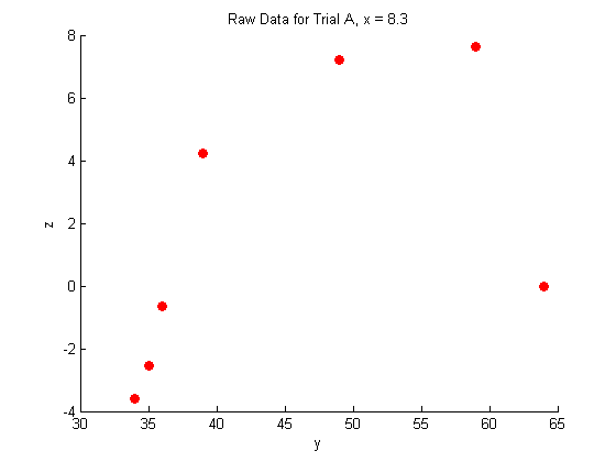
This is raw data from an experiment for three trials (a and b and c). The X and Y are independent variables, and we measured Z.

X_a = [8.3 8.3 8.3 8.3 8.3 8.3 8.3];
X_b = [11 11 11 11 11 11 11];
X_c = [14 14 14 14 14 14 14];

Y_a = [34 59 64 39 35 36 49];
Y_b = [39 32 27 61 52 57 65];
Y_c = [63 33 38 50 54 68 22];

Z_a = [-3.59833 7.62 0 4.233333333 -2.54 -0.635 7.209];
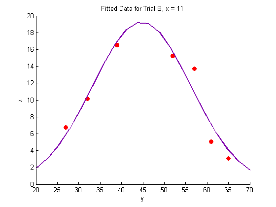
Z_b = [16.51 10.16 6.77 5.08 15.24 13.7 3.048];
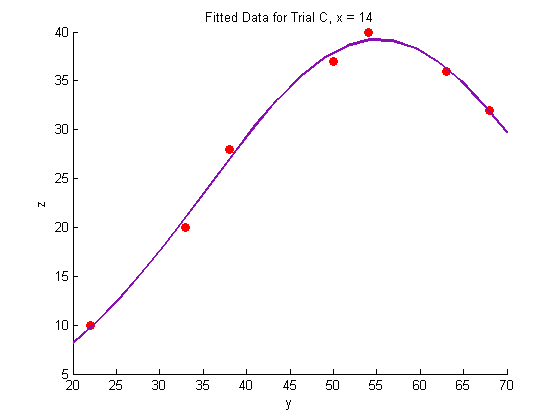
Z_c = [36 20 28 37 40 32 10];

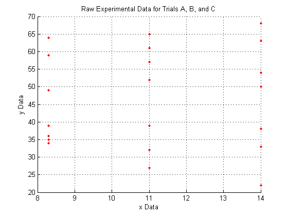
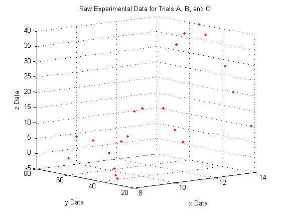
Plotting the raw data for all three trials:

As you can see, the raw data does not look like very much, and it is pretty hard to interperet what it could mean.

We do see, however, that since X_a is all of one value, X_b is all of another value, and X_c is all of a third, that the data lies entirely on three separate planes.

figure
hold on     % Use this to plot multiple series on a single figure
plot3(X_a,Y_a,Z_a,'.','Color',pcol)
plot3(X_b,Y_b,Z_b,'.','Color',pcol)
plot3(X_c,Y_c,Z_c,'.','Color',pcol)
hold off    % Use this to make sure the next plot command will not
% try to plot on this figure as well.
title('Raw Experimental Data for Trials A, B, and C')
xlabel('x Data')
ylabel('y Data')
zlabel('z Data')
grid on     % 3D data is easier to visualize with the grid. Normally
% the grid defaults to 'on' but using the 'hold on'
% command as we did above causes the grid to default to
% 'off'

A note on the view:

The command

 view(Az,El)

lets you view a 3D plot from the same viewpoint each time you run the code. To determine the best viewpoint to use, use the click the 'Rotate 3D' icon in the figure toolbar (it looks like a box with a counterclockwise arrow around it), and drag your plot around to view it from different angles. You will notice the text "Az: ## El: ##" appear in the lower left corner of the figure window. This stands for Azimuth and Elevation which represent a point in spherical coordinates from which to view the plot (the radius is fixed by the axes sizes). The command used here will always display the plot from azimuth = -39, and elevation = 10.

view(-39,10)

A closer look at the raw data:

figure
hold on
plot(Y_a,Z_a,'o','MarkerFaceColor',pcol,'MarkerEdgeColor','none')
title('Raw Data for Trial A, x = 8.3')
xlabel('y')
ylabel('z')
hold off

figure
hold on
plot(Y_b,Z_b,'o','MarkerFaceColor',pcol,'MarkerEdgeColor','none')
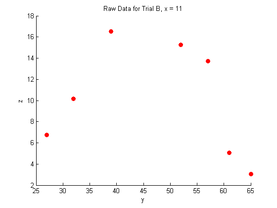
title('Raw Data for Trial B, x = 11')
xlabel('y')
ylabel('z')
hold off

figure
hold on
plot(Y_c,Z_c,'o','MarkerFaceColor',pcol,'MarkerEdgeColor','none')
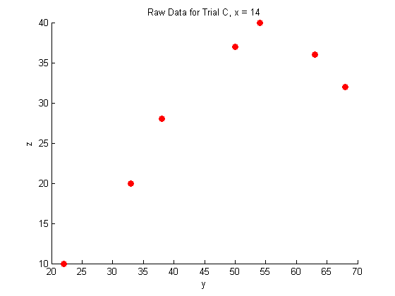
title('Raw Data for Trial C, x = 14')
xlabel('y')
ylabel('z')
hold off

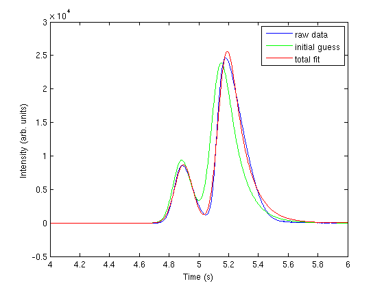
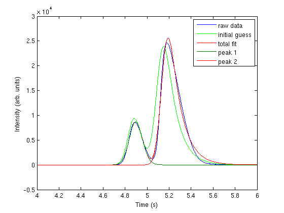
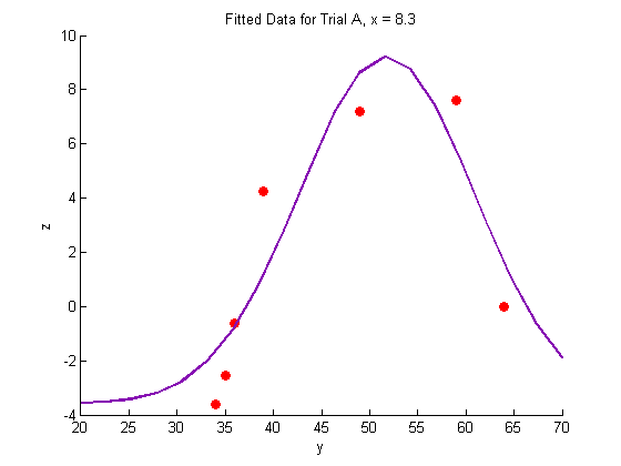
Fitting the raw data:

In this case, we expect the data to fit the shape of a binomial distribution, so we use the following fit function with three parameters:

    function v = mygauss(par, t)
        A  = par(1);
        mu = par(2);
        s  = par(3);

        v=A*exp(-(t-mu).^2./(2*s.^2));
    end

Fitting the data

res = 20;
Yfit=linspace(20,70,res);

% Dataset A
guesses=[20, 40, 20];
[pars residuals J]=nlinfit(Y_a, Z_a-min(Z_a), @mygauss, guesses);

A1=pars(1);
mu1=pars(2);
s1=pars(3);

Zfitfun_a=@(y) A1*exp(-(y-mu1).^2./(2*s1.^2))+min(Z_a);
% Note: We have to shift the dataset up to zero because a gaussian
% typically cannot go below the horizontal axis

% Generate a fit-line through the data

Zfit_a=Zfitfun_a(Yfit);

% Dataset B
guesses=[10, 25, 20];
[pars residuals J]=nlinfit(Y_b, Z_b, @mygauss, guesses);

A2=pars(1);
mu2=pars(2);
s2=pars(3);

Zfitfun_b=@(y) A2*exp(-(y-mu2).^2./(2*s2.^2));

% Generate a fit-line through the data
Zfit_b=Zfitfun_b(Yfit);

% Dataset c
guesses=[20, 60, 20];
[pars residuals J]=nlinfit(Y_c, Z_c, @mygauss, guesses);

A3=pars(1);
mu3=pars(2);
s3=pars(3);

Zfitfun_c=@(y) A3*exp(-(y-mu3).^2./(2*s3.^2));

% Generate a fit-line through the data
Zfit_c=Zfitfun_c(Yfit);

Plotting the fitted data:

% Trial A
figure
hold on
plot(Y_a,Z_a,'o','MarkerFaceColor',pcol,'MarkerEdgeColor','none')
title('Fitted Data for Trial A, x = 8.3')
xlabel('y')
ylabel('z')
plot(Yfit,Zfit_a,'Color',lcol,'LineWidth',2)
hold off

% Trial B
figure
hold on
plot(Y_b,Z_b,'o','MarkerFaceColor',pcol,'MarkerEdgeColor','none')
title('Fitted Data for Trial B, x = 11')
xlabel('y')
ylabel('z')
plot(Yfit, Zfit_b,'Color',lcol,'LineWidth',2)
hold off

% Trial C
figure
hold on
plot(Y_c,Z_c,'o','MarkerFaceColor',pcol,'MarkerEdgeColor','none')
title('Fitted Data for Trial C, x = 14')
xlabel('y')
ylabel('z')
plot(Yfit,Zfit_c,'Color',lcol,'LineWidth',2)
hold off

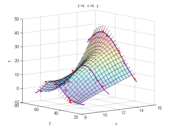
Generate a surface plot:

For every point along the fit-line for dataset A, connect it to the corresponding point along the fit-line for dataset B using a straight line. This linear interpolation is done automatically by the surf command. If more datasets were available, we could use a nonlinear fit to produce a more accurate surface plot, but for now, we will assume that the experiment is well-behaved, and that 11 and 8.3 are close enough together that we can use linear interpolation between them.

Interpolate along the fit lines to produce YZ points for each data series (X):

Fits through the fits

Yspace = linspace(25,65,res);
Xs = [8.3; 11; 14];
Xspan1 = linspace(8.3,14,res);
Xspan2 = linspace(8,14.3,res);
q = 0;
r = 0;
for i = 1:res
    Zs = [Zfitfun_a(Yspace(i)); Zfitfun_b(Yspace(i)); Zfitfun_c(Yspace(i))];
    Yspan = linspace(Yspace(i),Yspace(i),res);
    p(:,i) = polyfit(Xs,Zs,2);
    for j = 1:res
        Zfit_fit(i,j) = polyval(p(:,i),Xspan1(j));
    end
end

Plot a surface through the fits through the fits

figure
hold all
surf(Xspan1,Yspace,Zfit_fit,'EdgeColor','black');   % Generate the surface
%surf(Xsurf,Ysurf,Zsurf,'EdgeColor','black');   % Generate the surface

% plot leading and lagging lines (just for show!)
for i = 1:res
    Zs = [Zfitfun_a(Yspace(i)); Zfitfun_b(Yspace(i)); Zfitfun_c(Yspace(i))];
    Yspan = linspace(Yspace(i),Yspace(i),res);
    plot3(Xspan2,Yspan,polyval(p(:,i),Xspan2),'Color','black')
end

%Plot the raw data:
plot3(X_a,Y_a,Z_a,'o','markersize',5,'MarkerFaceColor',pcol,'MarkerEdgeColor','none')
plot3(X_b,Y_b,Z_b,'o','markersize',5,'MarkerFaceColor',pcol,'MarkerEdgeColor','none')
plot3(X_c,Y_c,Z_c,'o','markersize',5,'MarkerFaceColor',pcol,'MarkerEdgeColor','none')

%Plot the fit lines:
plot3(linspace(8.3,8.3,res),Yfit,Zfit_a,'Color',lcol,'LineWidth',2)
plot3(linspace(11,11,res),Yfit,Zfit_b,'Color',lcol,'LineWidth',2)
plot3(linspace(14,14,res),Yfit,Zfit_c,'Color',lcol,'LineWidth',2)
view(-39,10)
alpha(.2)   % Make the plot transparent
title('z vs. x vs. y')
xlabel('x')
ylabel('y')
zlabel('z')
grid on

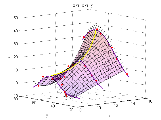
Add a line through the max

We must minimize the negative of each of our initial three fits to find the maximum of the fit.

f1 = @(y) -Zfitfun_a(y);
f2 = @(y) -Zfitfun_b(y);
f3 = @(y) -Zfitfun_c(y);

Ystar_a = fminbnd(f1,0,100);
Ystar_b = fminbnd(f2,0,100);
Ystar_c = fminbnd(f3,0,100);

Ystars = [Ystar_a; Ystar_b; Ystar_c];
Zstars = [Zfitfun_a(Ystar_a); Zfitfun_b(Ystar_b); Zfitfun_c(Ystar_c)];

hold on
plot3(Xs,Ystars,Zstars,'o','markersize',7,'MarkerFaceColor','white')

xy = polyfit(Xs,Ystars,2);
xz = polyfit(Xs,Zstars,2);

plot3(Xspan1,polyval(xy,Xspan1),polyval(xz,Xspan1),'Color','yellow','LineWidth',2)

A note on colormaps

To edit the color of the surface, you can apply a colormap. Matlab has several built-in colormaps (to see them, type 'doc colormap' in the Command Window. As you see here, however, we are using our own colormap, which has been stored in the file 'mycmap.mat'

To modify a colormap, type

 cmapeditor

in the Command Window or click 'Edit' 'Colormap...' in the figure window. For instructions on how to use the colormap editor, type 'doc colormapeditor' in the Command Window. If you have 'Immediate apply' checked, or you click 'Apply' the colormap will load onto the figure. To save a colormap, type the following into the Command Window:

 mycmap = get(gcf,'Colormap')
 save('mycmap')
s = load('mycmap.mat');
newmap = s.mycmap;
set(gcf,'Colormap',newmap)  % See corresponding 'Note on colormaps')
end

Summary

Matlab offers a lot of capability to analyze and present data in 3-dimensions.

% categories: plotting, data analysis
Read and Post Comments

Next Page »